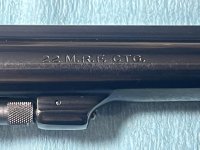
Being this is a .22 Magnum, the most powerful rimfire in the world and would blow half your head clean off, you've gotta ask yourself one question: "Do I feel lucky?"
I was feeling lucky tonight and wanted to do something fun while I waited for my Security Six special shim shipment to show.
Project name: A Little Harry
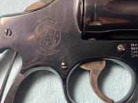
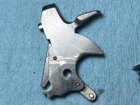
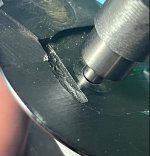
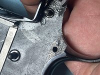
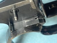
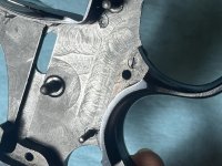
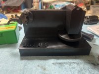
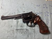
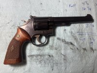
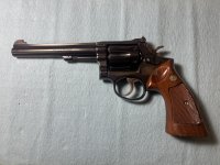
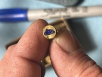
Little Harry is a 48-2 in .22 WMR that was made in 1974. It has a 6" barrel, target stocks, and a damn ugly trigger.
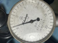
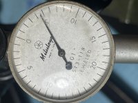
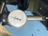
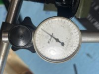
I knew I was going to be working on Harry soon, so during my last range trip I did a strain screw loosening reliability test. With the strain screw fully seated the hammer tension was 72 ounces. Half a turn out was 60 ounces and a full turn out was 52 ounces but that didn't matter because anything over 1/2 turn out gave light strikes. That made things simple: stay above 60 ounces with this one.
That range trip also gave me something I would need during the work: empty cases. Dropping the hammer on an empty rimfire chamber is bad juju and I didn't have any rimfire snap caps. My wife looked at me a bit strangely when I handed her 6 empty cases and asked her to verify that they really were empty. Then again, she's been sure that I'm a few bottles short of a 6 pack for a while. The empty cases were marked with a blue sharpie but unfortunately that wore off with handling. Note to self: get the right snap caps for rimfires.
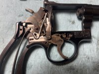
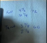
The initial trigger pull tests showed 4 1/2 lbs single action and 10 1/4 lbs double action. The single action break had a fair amount of creep and the double action pull was peaky and uneven. Backing the strain screw out 1/2 turn dropped the numbers a bit to 3 3/8 lbs single action and 8 1/2 lbs double action. The peaky double action pull seemed to get worse with the screw backed out.
Help me Jerry Kuhnhausen, you're my only hope.
I was feeling lucky tonight and wanted to do something fun while I waited for my Security Six special shim shipment to show.
Project name: A Little Harry
Little Harry is a 48-2 in .22 WMR that was made in 1974. It has a 6" barrel, target stocks, and a damn ugly trigger.
I knew I was going to be working on Harry soon, so during my last range trip I did a strain screw loosening reliability test. With the strain screw fully seated the hammer tension was 72 ounces. Half a turn out was 60 ounces and a full turn out was 52 ounces but that didn't matter because anything over 1/2 turn out gave light strikes. That made things simple: stay above 60 ounces with this one.
That range trip also gave me something I would need during the work: empty cases. Dropping the hammer on an empty rimfire chamber is bad juju and I didn't have any rimfire snap caps. My wife looked at me a bit strangely when I handed her 6 empty cases and asked her to verify that they really were empty. Then again, she's been sure that I'm a few bottles short of a 6 pack for a while. The empty cases were marked with a blue sharpie but unfortunately that wore off with handling. Note to self: get the right snap caps for rimfires.
The initial trigger pull tests showed 4 1/2 lbs single action and 10 1/4 lbs double action. The single action break had a fair amount of creep and the double action pull was peaky and uneven. Backing the strain screw out 1/2 turn dropped the numbers a bit to 3 3/8 lbs single action and 8 1/2 lbs double action. The peaky double action pull seemed to get worse with the screw backed out.
Help me Jerry Kuhnhausen, you're my only hope.
Attachments

Last edited: