Here is a description of my project to construct an LED lighting system for my Dillon 550 loader. The final cost to me was $0.00 because I hade most/all the parts available in my electronic junque parts boxes normally used for my ham radio/electronics hobby.
I needed to present this using 2 separate threads because I used more than 5 pictures.
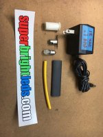
Picture 1 shows the total complement of parts I assembled. Not described below are the two pieces of heat shrink tubing - a 1/2" and 1/4" piece - needed to protect the electrical connections and provide a little friction fit inside the holder.
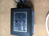
The 2nd picture highlights the surplus "wall wart' power supply needed to power the light. The supply I had is way over the actual needed current capacity, and actually any power supply rated with the voltage of the LED bulb will work.
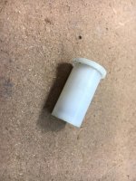
The 3rd picture is that of the nylon bushing used in the Dillon 550/650 etc. powder measure - I had an extra, used powder bushing obtained from a purchase of used eBay parts years ago. The bushing fits perfectly into the tool head's center hole as used by the commercially available after market LED lights costing $20-$30 (which gave me the idea for this project).
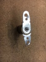
The 4th picture is an unused bayonet base pilot light holder normally found in a vintage radio set from the '50's or '60's. This particular model would have been held in place in the radio using a rubber grommet sized to the bulb to illuminate the dial of the radio.
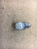
The 5th picture is the actual 4-LED bulb used for illumination. I use these in my ham radio equipment restorations as replacements for incandescent dial and metering lights with the bayonet bases such as #47, #45 and #43 incandescent BA9 bulbs. I source these from SuperBrightLeds.com in quantities of 10 each depending upon the voltage I most recently ran out of, such as 6 volts or 12 volts. Net cost for the bulb used here is $1.98 in single quantities. The supplier's stock number for the 12 volt bulb is :
BA9S-W4-90-12VAC cool white 90 degree 12V
and will work using AC or DC interchangeably.
See part 2 for the rest of the story.
I needed to present this using 2 separate threads because I used more than 5 pictures.
Picture 1 shows the total complement of parts I assembled. Not described below are the two pieces of heat shrink tubing - a 1/2" and 1/4" piece - needed to protect the electrical connections and provide a little friction fit inside the holder.
The 2nd picture highlights the surplus "wall wart' power supply needed to power the light. The supply I had is way over the actual needed current capacity, and actually any power supply rated with the voltage of the LED bulb will work.
The 3rd picture is that of the nylon bushing used in the Dillon 550/650 etc. powder measure - I had an extra, used powder bushing obtained from a purchase of used eBay parts years ago. The bushing fits perfectly into the tool head's center hole as used by the commercially available after market LED lights costing $20-$30 (which gave me the idea for this project).
The 4th picture is an unused bayonet base pilot light holder normally found in a vintage radio set from the '50's or '60's. This particular model would have been held in place in the radio using a rubber grommet sized to the bulb to illuminate the dial of the radio.
The 5th picture is the actual 4-LED bulb used for illumination. I use these in my ham radio equipment restorations as replacements for incandescent dial and metering lights with the bayonet bases such as #47, #45 and #43 incandescent BA9 bulbs. I source these from SuperBrightLeds.com in quantities of 10 each depending upon the voltage I most recently ran out of, such as 6 volts or 12 volts. Net cost for the bulb used here is $1.98 in single quantities. The supplier's stock number for the 12 volt bulb is :
BA9S-W4-90-12VAC cool white 90 degree 12V
and will work using AC or DC interchangeably.
See part 2 for the rest of the story.