HomeSmith Custom Shop: The Faux Pinto Thread

Joined
Jul 25, 2017
Messages
1,143
Reaction score
6,716
Location
Arizona
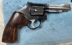
Sharp-eyed readers of the Rustbucket thread noticed that there was a second frame that went along for the ride during the metal finishing and bluing process. The second frame was another homely Model 15-3 that needed a facelift.

I've done a few two-tone projects but most of those kind of "ended up" that way. This time we have a plan and a purpose....

Welcome to the Faux Pinto thread.

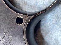
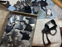
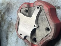
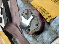
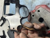
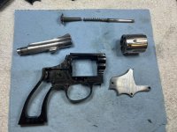
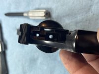
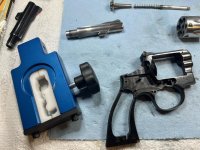
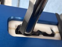
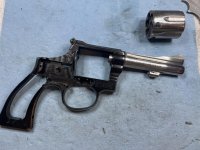
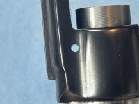
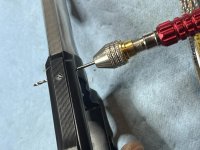
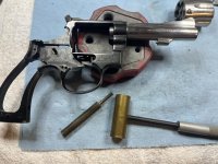
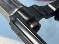
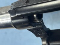
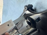
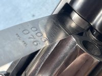
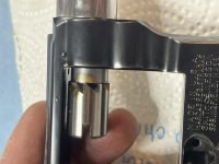
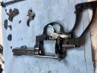
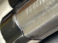
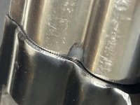
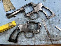
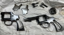
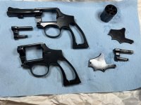
Our soon-to-be-pinto was stripped down to the frame, yoke, and sideplate, and was treated to the same metal prep and bathroom rust bluing that was done to Rustbucket. There are lots of details about that in the other thread. Here are a few pics of the two frames as they went through the process.
 

Attachments

  • IMG_5356.jpg
    IMG_5356.jpg
    183.3 KB · Views: 76
  • IMG_5373.jpg
    IMG_5373.jpg
    146.2 KB · Views: 72
  • IMG_5393.jpg
    IMG_5393.jpg
    93.3 KB · Views: 75
  • IMG_5427a.jpg
    IMG_5427a.jpg
    90.4 KB · Views: 69
  • IMG_5552.jpg
    IMG_5552.jpg
    120 KB · Views: 74
Last edited:
Register to hide this ad
With Rustbucket out of the way and the Tetanus Specials (did I mention that there are two now? :rolleyes:) waiting patiently, it was time to work through the Pinto project.

I wasn't really happy with the way the sideplate had turned out during the bathroom bluing extravaganza. I'm not sure if the 25% solution didn't lay down enough of a base layer or if I was just too heavy handed with the carding wheel (or both), but the sideplate ended up with a sort of light brown color around all the edges where the bluing just didn't stick around. During a test fit of the pieces to compare the colors, I noticed something that I had missed during my initial inspection of the gun: the sideplate had been replaced by someone else and really did not fit well.

I have to admit that I may have said a few words that would not make my Grandmother proud. The emotional support llama wasn't much help: he had noticed the sideplate issue first and was hiding inside a bottle of Jameson. I was ticked off enough that my secondary plan was to re-blue the sideplate, the original barrel, and the original cylinder, toss it all back together and just put the darn thing on Gunbroker.

After spending an hour or so reorganizing my work area to distract myself, I was about to start stripping the old blue off of the original barrel when the emotional support llama staggered over and started yelling at me about how we hadn't given up when the Germans bombed Pearl Harbor and we shouldn't give up now. In the middle of a barely coherent rant about how Gandalf had always told Harry Potter to "live long and use the force", he reminded me that there was a box full of sideplates under the workbench and that I should try to find one in there that fit better.

After about 30 minutes of semi-successful sideplate test fits, I found two that actually fit rather well. Unfortunately the one that fit the best had a huge line of Pachmayr Pits (TM) that went right through the logo. The next best fitting sideplate turned out to be stainless. The emotional support llama had passed out behind the safe so he wasn't any help. I had a talk with myself and we decided to go with the stainless sideplate and press on with the Pinto Project.

It took longer to put away all the sideplates that didn't fit than it did to clean up the replacement. A few minutes of 220, 320, 400, 600, 800, 1000, 1200, and 2500 grit sandpaper on a small block had the replacement sideplate looking nice and pretty. We were back in business.
 

Attachments

  • IMG_5733.jpg
    IMG_5733.jpg
    104.5 KB · Views: 66
  • IMG_5726.jpg
    IMG_5726.jpg
    176.4 KB · Views: 59
  • IMG_5736.jpg
    IMG_5736.jpg
    115.4 KB · Views: 61
  • IMG_5738.jpg
    IMG_5738.jpg
    120.5 KB · Views: 60
  • IMG_5737.jpg
    IMG_5737.jpg
    105 KB · Views: 67
Last edited:
After a quick putting-together of the insides to make sure that nothing was going to drag on the new sideplate (they have two sides :rolleyes:), I faced my next issue: finding the parts again.

Way back before the metal prep started, I had begun this project by finding a stainless barrel that threaded on at 11 o'clock and a matching cylinder that fit the yoke, headspaced correctly, and was close enough on timing that it would be easy to do the final fitting. That was before I decided to bag it all and go back to the original parts. The new parts that I had so carefully selected and prepped had been mixed in with all the other spare parts during the reorganization....and it had been a complete reorganization, going from boxes of parts to hanging racks. Every piece had been moved.

Pictures might be helpful here. I've mentioned before that I've been building a parts library with the hopes of someday doing this for more than just entertainment....this is part of it. Somewhere in there were my barrel and cylinder. I needed .38 special parts, so at least I could narrow down the search somewhat.
 

Attachments

  • IMG_5715a.jpg
    IMG_5715a.jpg
    97.3 KB · Views: 91
  • IMG_5716a.jpg
    IMG_5716a.jpg
    99.5 KB · Views: 85
  • IMG_5739.jpg
    IMG_5739.jpg
    140.1 KB · Views: 74
Now that I knew were all my parts were again, it was time to install the barrel. The rear sight was reinstalled first so that it could be used as a reference for straightness of the assembly, then the MGW action wrench was put together and we went to visit the big vise in the garage. After putting the "only ever used for barrel installs" padded vise jaws in place, a few quick pulls of the handle had the barrel on and aligned.

It's always nice when the barrel pin hole and channel line up. I think that may have been the first thing that went right with this project.
 

Attachments

  • IMG_5742.jpg
    IMG_5742.jpg
    57.6 KB · Views: 55
  • IMG_5743.jpg
    IMG_5743.jpg
    137.5 KB · Views: 55
  • IMG_5744.jpg
    IMG_5744.jpg
    61.6 KB · Views: 59
  • IMG_5745.jpg
    IMG_5745.jpg
    139.4 KB · Views: 65
  • IMG_5746.jpg
    IMG_5746.jpg
    69.8 KB · Views: 59
There's been some discussion in another thread about how to remove the barrel pin (I start it with a #5 cup tip punch and finish with a #2) but there hasn't been much discussion about putting the pin back in.

Even when the frame hole and barrel channel appear to be lined up, I run a #50 drill bit through in a handheld tool just to make sure that there are no little burrs or built up glock in the way.

I like to put a very slight bend in the pin just so it locks in place better. In this case, the original pin already had a slight bend so no adjustment was needed.

When I first started doing this, I used the cup tip punches for both removal and reassembly. Removal was easy, but reassembly required 17.37 hands to hold the frame, hold the pin, hold the punch, line up the punch, and hit it all with a hammer. Using scotch tape to tape the punch and pin together in line with each other helped, but it was still a pain.

I realized pretty quickly that the cup tip punches were really only needed for taking the pins out. Putting them in could be done with a brass (not steel) hammer and punch. Put the frame on your bench block, hold the pin like a nail, and tap it in with the brass hammer. The last tiny bit of movement to center the pin in the frame is done using the brass hammer and brass punch. Yes, the face of the hammer and punch get deformed by the pin, but that's the idea. Brass is soft and can be reshaped. My steel hammers all have the striking face polished to look like mirrors so that there is no pattern transfer from the hit-er to the hit-ee. When my brass hammers start to look like the surface of the moon, I use my polished steel hammer and my polished steel anvil to smooth them out again.

Anyway...a little tappy tappy and we were ready to have dinner.
 

Attachments

  • IMG_5747.jpg
    IMG_5747.jpg
    100.6 KB · Views: 63
  • IMG_5748.jpg
    IMG_5748.jpg
    136.2 KB · Views: 59
  • IMG_5749.jpg
    IMG_5749.jpg
    79.4 KB · Views: 63
  • IMG_5750.jpg
    IMG_5750.jpg
    69.1 KB · Views: 62
With the barrel installed and the grilled pork chops eaten, it was time to move on to the initial fitting of the cylinder: does it fit in the window and does is spin freely? The answers were Mostly and No. :confused:

Good news first: the rear gauge checked out with the .060" minimum gauge entering the gap and the .068" maximum gauge not entering. There was no end shake, so that got added to the list of things to address. Before we could really look at end shake, the barrel to cylinder gap needed to be checked to make sure that the lack of end shake was not because the cylinder was butted up against the barrel. There was no contact, but it was close. The cylinder gap was a rather tight .003"...too close, but that shouldn't be what was preventing the cylinder from turning easily.

One thing at a time.

The 90 degree facing tool and handle were assembled, some Viper Venom was dripped onto the cutting surfaces, and we started spinning. As usual, the end of the barrel wasn't quite square. I cut until there was full contact all the way around and stopped to check the gap. It's hard to tell in the picture, but the .006" gauge is in the gap and hanging from the gun without being supported by the bench.

We'll call that good for now, pending later measurements and a test fire.
 

Attachments

  • IMG_5752.jpg
    IMG_5752.jpg
    70.4 KB · Views: 42
  • IMG_5753.jpg
    IMG_5753.jpg
    72.8 KB · Views: 43
  • IMG_5754.jpg
    IMG_5754.jpg
    89.1 KB · Views: 47
  • IMG_5769.jpg
    IMG_5769.jpg
    80.1 KB · Views: 48
  • IMG_5770.jpg
    IMG_5770.jpg
    49.7 KB · Views: 44
Trimming the barrel meant that the forcing cone also got trimmed, so the forcing cone gauge was plopped in....wait, I take that back. The forcing cone gauge was pushed into place because it was a tight fit. The gauge showed that the cone was at the minimum spec. Time for more cutting.

I didn't grab a picture of the 11 degree forcing cone cutter at work, but hopefully that isn't too hard to visualize. After a couple of turns and the addition of the appropriate amounts of dog hair and paper towel fuzz, the gauge did actually plop in and the forcing cone was now closer to the maximum end of the measurement spectrum. That's where I wanted it to fall because I have a feeling that we may need to add just a touch more cylinder gap later.
 

Attachments

  • IMG_5771.jpg
    IMG_5771.jpg
    65.1 KB · Views: 47
  • IMG_5772.jpg
    IMG_5772.jpg
    66.6 KB · Views: 47
  • IMG_5774.jpg
    IMG_5774.jpg
    68.3 KB · Views: 44
Now that our gap is bigger, does the cylinder turn freely?

Nope. :(

Time for some troubleshooting.

Does the bare cylinder with nothing installed spin freely on the yoke? Yes, it does.

After installing the ejector star, does the cylinder still spin freely on the yoke? Yes, it does.

With the ejector rod, center pin, and springs installed, does the cylinder spin freely on the yoke. No. It fits but drags badly.

Meh...that's easy. We'll just ream the inside of the yoke barrel and we'll be golden. No problem. The yoke reamer was lubed up and after a little spinny spinny we had a nice clean properly spec'd yoke barrel.

Everything spins freely now, right? Nope. It's better but there is still a drag.

Is the ejector rod straight? Oh heck no. It looks like a dog wagging it's tail instead of a spinning shaft. Before this project a bent ejector rod always meant that the threaded portion of the ejector rod was tweaked out of alignment. That was true this time, but we also had a bent center pin. Whoever bent this one done bent it good.

To straighten the center pin, I laid it on my bench block, rolled it back and forth, and every time I was able to see light between the pin and the block it got hammered lightly.

Side topic: I have two bench blocks. One is this one: non-marring bench block, and the other is a large steel weight from a CMP trigger pull measuring set similar to this one. The non-marring bench block gets used much more, but when I need the equivalent of a small anvil I bring out the solid steel one.

The ejector rod was also bent at the threads but I didn't want to bugger up the threads by pounding on it. The handy dandy Power Custom ejector rod straightening fixture was brought out, all the pieces were put were the pieces go, and we did a test spin against the dial indicator. Only .022" of runout. :eek:

Tweak, tweak, turn, turn, measure, tweak, turn, measure, tweak the other way because we went too far, turn, measure, and we finally got to .002" of runout on the ejector rod.

Does the assembly spin freely on the yoke now? You betcha. Let's put it in the frame and enjoy our triumph.
 

Attachments

  • IMG_5751.jpg
    IMG_5751.jpg
    54.8 KB · Views: 44
  • IMG_5757.jpg
    IMG_5757.jpg
    94 KB · Views: 43
  • IMG_5760.jpg
    IMG_5760.jpg
    68.4 KB · Views: 44
  • IMG_5762.jpg
    IMG_5762.jpg
    68.9 KB · Views: 42
  • IMG_5763.jpg
    IMG_5763.jpg
    68.4 KB · Views: 40
Last edited:
Our triumph was rather short lived.

The cylinder assembly would spin freely on the yoke, but when everything was back in the frame we still had something dragging. Grrr.

Are the ejector star lugs dragging on the recoil shield? Nope...coloring them with a sharpie and then spinning the cylinder resulted in no change to the sharpie.

Is the cylinder not parallel and one part is dragging on the barrel? Nope...daylight through the gap all the way around.

Cylinder stop? That's not even installed yet.

Yoke alignment? Nope. That's perfect.

What is it that I see happening right around the flat spot on the bottom of the threaded portion of the barrel? Let's put some magnification on that.

Apparently somewhere and somewhen during it's lifetime the cylinder was dropped or hit with something....probably the same event that bent the center pin and ejector rod. Keep in mind that the parts kits I get are from guns that are being destroyed. The folks that salvage the pieces prior to destruction aren't payed to take good care of the parts - they're paid to get it done and move on to the next one.

Some action with a safe edged file got rid of the burr and the 87th test spin actually worked. There was much rejoicing. I tried to spin the cylinder with my left hand and snap a picture with my right hand in an attempt to get a blurry picture of the cylinder spinning, but I'm not coordinated enough to make that work. Use your imagination.

Time to move on...
 

Attachments

  • IMG_5764.jpg
    IMG_5764.jpg
    73.3 KB · Views: 46
  • IMG_5776a.jpg
    IMG_5776a.jpg
    67 KB · Views: 55
  • IMG_5782.jpg
    IMG_5782.jpg
    66.7 KB · Views: 49
Last edited:
Honestly the rest of the putting together was pretty basic - just an exercise in validating proper fitment of the internal pieces and a trigger job.

The fitment review was necessary because I switched out the internal parts. The color case hardened service hammer and grooved trigger were replaced with a stainless hammer and slightly wider smooth combat trigger. The cylinder stop and rebound slide that matched the trigger and hammer were also used, but the original hand was retained because it gave me better timing than the one that was with the stainless parts.

Changing out the cylinder stop meant checking to ensure that the new stop would fit through the frame window, fit into the cylinder notches, and that it was withdrawn at the appropriate time in the cycle for everything to work correctly. While I was at it I used a stone to gently break the sharp edges of the stop to minimize the turn ring.

The wink between the hammer and rebound slide looked good, we had right, left, and neutral sing from the hand, the carry up was beautiful, and nothing was dragging.

The original strain screw had been shortened somewhat and provided 50 ounces of hammer tension with a stock hammer spring. The single action pull is right at 2 pounds and the double action pull is just under 8 pounds.
 

Attachments

  • IMG_5790.jpg
    IMG_5790.jpg
    133.7 KB · Views: 27
  • IMG_5798.jpg
    IMG_5798.jpg
    74.8 KB · Views: 20
  • IMG_5796.jpg
    IMG_5796.jpg
    87.1 KB · Views: 20
To complete the package, I stirred around in the pile of stocks and found a ratty old pair that need refinishing but feel good in my hand.

Assuming that we get a successful test fire and no mechanical problems pop up, the only other semi-major task to be done is to cut the front sight and install a red insert....but I want to practice that on some junk barrels before I do it on a nice one.

My schedule today isn't going to leave room for a range trip, so we'll all just have to wait until next weekend to find out how well it works. Stay tuned.

I'd like to do a few more projects like this in the future. Instead of starting a new thread for each gun, I'm planning on just stacking all the pinto-ish conversions into this thread.

I'd also like to invite anyone else who is working on similar projects to jump in and share what you're working on. Let's make it a party! :D
 

Attachments

  • IMG_5801a.jpg
    IMG_5801a.jpg
    105.7 KB · Views: 64
  • IMG_5802a.jpg
    IMG_5802a.jpg
    109.4 KB · Views: 55
Does this one count? It was a rough Canadian .455 with mods when I got it. Now reduced to K grip frame size, 625-10 barrel and cylinder. Ball detent front lockup. Modified scrap K grips. Round lanyard ring from one of the 80's foreign contract guns. DIY park finish on frame. Flat thumb latch assembly from an early Model 12.

1917a.jpg


Here's another one. It's polished in the white now. Not sure what finish it will get. I've since improved the look of the barrel-frame 'step' by tapering the sharp corners. I had a local trophy shop laser elngrave the barrel info. Semi-target trigger and modified hammer.

mg2.jpg
 
Last edited:
I’ll play. Some of you have met Bob, the 586/686 mishmash. Turns out he has issues.

First is a timing issue on one cylinder, carryup is almost there but not 100%. Second issue is mostly cosmetic but it bugs me.

The photo shows the front of the frame with lots of tool marks, it’s quite rough. With the new barrel, it is somewhat visible at the edge of the barrel.. I could true up the frame but would probably have to set the barrel back afterwards. Hmmmm.
 

Attachments

  • IMG_3294.jpg
    IMG_3294.jpg
    32.3 KB · Views: 47
@BTM - the engagement surface where the barrel bottoms out against the frame seems to be pretty well defined. As long as you don't touch that you should be able to clean up the tool marks without having to turn the barrel back. Less is more. You don't have to make the entire front of the frame pretty....just the parts that show after the barrel is in place.

Do you have a picture taken from the same angle with a barrel on the frame?
 
Here’s a couple pictures of the ugly part - Bob’s a shooter, not a safe queen but still. I was surprised, the old 586 barrel hid all of this.

This makes me wonder - is facing off and/or truing the frame a reasonable alternative to setting a barrel back?
 

Attachments

  • IMG_3369.jpg
    IMG_3369.jpg
    60.1 KB · Views: 33
  • IMG_3368.jpg
    IMG_3368.jpg
    60.5 KB · Views: 31
Here’s a couple pictures of the ugly part - Bob’s a shooter, not a safe queen but still. I was surprised, the old 586 barrel hid all of this.

This makes me wonder - is facing off and/or truing the frame a reasonable alternative to setting a barrel back?

I've used a stone to clean up a frame and get that last little bit of rotation to set a barrel, but never enough for a full turn.

If I were working on Bob, I think my approach would be to mark the exposed areas and use a file and stone to smooth them out, then use a 10" buffing wheel to "melt" the edge. I was taught never to put a square corner into a buffing wheel because it would round off the corner and make it look "melted"...here, I think I would do that on purpose to smooth out that transition.
 
Before today's range trip I swapped out the Trooper stocks on the Faux Pinto for a set of factory target stocks just to see how they looked, and they looked good enough to stay.

Function was 100% in single and double action with nice strong primer hits.

I seem to have gotten the barrel on reasonably straight. :rolleyes:

I think we'll call this one done. :D
 

Attachments

  • IMG_5864a.jpg
    IMG_5864a.jpg
    92 KB · Views: 41
  • IMG_5865a.jpg
    IMG_5865a.jpg
    77.9 KB · Views: 36
Back
Top