HomeSmith Tuneup: Spirits of '76

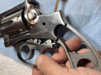
Once I was satisfied that the push-off was not going to be a further issue, it was time to tear down the rest of the gun.

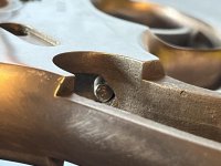
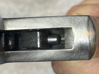
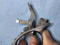
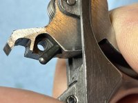
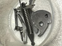
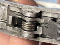
This time I discovered something. Everyone else in the world probably knew this already and I've just been slow on the uptake, but I apparently have been removing the trigger group from Ruger revolvers that wrong/hard way for 30 years. I've always gone in from the back, through the grip frame, with a punch and pushed on the plunger from that direction. It always works, but it usually takes a try or two because the punch slips off the plunger.

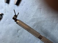
This go 'round I took some extra time to look at the mechanism and an idea hit me. Way back in the late 1900's when I was working on the counter in an auto parts store we were always given these goofy little screwdrivers as promo items. Small handle, square shaft, the logo of whatever company wanted more of our business at the moment on the handle, and a pen clip so that it would fit into your shirt pocket and tear a hole in your shirt when you bent over and/or stab you when you pulled a heavy box down off of a shelf. Did I still have one of those laying around?

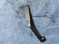
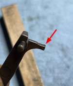
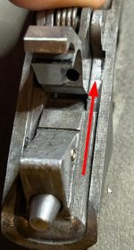
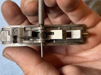
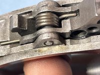
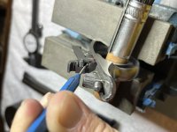
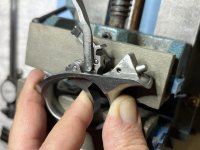
I did. And as a bonus, it actually had a hollow ground tip. Would this goofy thing fit in through the hammer window at the top of the frame and reach the plunger? It sure did, and the square shaft mated up with the frame perfectly. Rock the goofy screwdriver back and bloop, there's a trigger assembly in my hand.

As the great philosopher Bugs Bunny would say, "What a maroon." All this time...........
 

Attachments

  • IMG_2351.jpg
    IMG_2351.jpg
    86.2 KB · Views: 10
  • IMG_2352.jpg
    IMG_2352.jpg
    83.3 KB · Views: 9
  • IMG_2353.jpg
    IMG_2353.jpg
    68.3 KB · Views: 10
  • IMG_2354.jpg
    IMG_2354.jpg
    121.2 KB · Views: 11
So now for the thing that can't be done by mere mortals: taking apart a Ruger trigger group.

Step 1: Pull the trigger halfway back.

Step 2: Turn the assembly so that the transfer bar is on the bottom. It will fall out onto the bench.

Step 3: Pull trigger all the way back.

Step 4: Put your thumb over the swivel point of the hand/cylinder pawl. There is a plunger and spring behind the hand. I've never had one go Zing! but it's a good idea to put your thumb there just in case.

Step 5: Pull the hand off of the trigger.

Step 6: Using a pair of non-serrated needle nose pliers, remove the plunger and spring.

Step 7: Put all these parts into your patent pending small parts retaining bucket (a laundry soap measuring cup/lid)

At this point you'll have a beautiful view of the trigger return spring.
 

Attachments

  • IMG_2356.jpg
    IMG_2356.jpg
    98.9 KB · Views: 6
  • IMG_2357.jpg
    IMG_2357.jpg
    61.7 KB · Views: 5
  • IMG_2358.jpg
    IMG_2358.jpg
    70 KB · Views: 5
  • IMG_2360.jpg
    IMG_2360.jpg
    91.7 KB · Views: 5
  • IMG_2361.jpg
    IMG_2361.jpg
    116 KB · Views: 6
Now it's time for the only special tool you need: the $9 machinist parallel clamp that you bought from that jungle website.

Step 8: Attach the parallel clamp so that one leg is on top of the trigger return screw and the other leg is on the bottom rear of the trigger. You don't have to clamp hard...you're only holding, not clamping.

Step 9: When you have the clamp tension right, you can use a dental pick to reach in and push out the small pin that holds the trigger/spring assembly into the trigger guard. If you feel like you need a hammer something is wrong. Just fiddle with your clamp until the trigger/spring assembly is centered in the opening and the small pin will push out easily.

Step 10: Remove the clamp and separate the trigger and spring from the trigger guard.
 

Attachments

  • IMG_2366.jpg
    IMG_2366.jpg
    107.6 KB · Views: 5
  • IMG_2368.jpg
    IMG_2368.jpg
    103.5 KB · Views: 5
  • IMG_2369.jpg
    IMG_2369.jpg
    106 KB · Views: 5
  • IMG_2370.jpg
    IMG_2370.jpg
    124.4 KB · Views: 5
Step 11: Reattach the clamp just like it was before on the trigger...one side on the spring, the other side on the bottom of the trigger.

Step 12: Using a brass punch, push the hollow pin out to the side. Again, if you need a hammer something is wrong. When the clamp tension is correct the hollow pin will just push out.

Step 13: Put the clamp and trigger inside a plastic bag and slowly release the tension on the clamp, allowing the spring to come away from the trigger in a controlled manner.

Step 13a: If you chose not to use the plastic bag, search around under the bench and in the corners of the room for the spring that went flying when you released the clamp. A magnet tool can be helpful for retrieving the spring from under the shelf farthest away from the bench.:rolleyes:
 

Attachments

  • IMG_2371.jpg
    IMG_2371.jpg
    61.2 KB · Views: 3
  • IMG_2372.jpg
    IMG_2372.jpg
    92.7 KB · Views: 4
  • IMG_2373.jpg
    IMG_2373.jpg
    91.5 KB · Views: 3
  • IMG_2378.jpg
    IMG_2378.jpg
    78 KB · Views: 3
  • IMG_2374.jpg
    IMG_2374.jpg
    109.8 KB · Views: 4
Now is a good time for a bit of fluff and buff while everything is spread out.

Step 14: Using sandpaper (with a flat sanding block) or a ceramic stone, smooth out the corners of the transfer bar. It doesn't have to be polished...just smoothed enough so that it slides easily inside the frame.

Step 15: Smooth the sharp corners on the hand/cylinder pawl where it contacts the trigger guard (arrows).

Step 16: Smooth the corresponding area in the trigger guard.

Step 17: Sand or stone the sides of the trigger to remove any corrosion. Keep all of your strokes in the same direction.

I also took the time here to address some issues with the trigger bevel and sear. If you go back a few posts, the pictures show the trigger bevel and sear marked up with black sharpie and the wear patterns from the cycling the action a few times.

The bevel was smoothed out, the transition was rounded very slightly, and the sear was dulled just a tiny amount. Whoever was in this gun before me sharpened the sear so much that it actually shaved some hair off my arm. I took exactly 4 strokes on the sharpened edge of the sear with a ceramic stone to dull it up a bit. Why 4? It seemed like a good place to start. I expected to have to come back and do more, but the 4 strokes turned out to be just about right. The next time I have it apart I may do one more, but no more than that.
 

Attachments

  • IMG_2402.jpg
    IMG_2402.jpg
    171.9 KB · Views: 4
  • IMG_2389a.jpg
    IMG_2389a.jpg
    253.5 KB · Views: 4
  • IMG_2390a.jpg
    IMG_2390a.jpg
    276.1 KB · Views: 4
  • IMG_2411a.jpg
    IMG_2411a.jpg
    51.2 KB · Views: 4
  • IMG_2401.jpg
    IMG_2401.jpg
    166.6 KB · Views: 4
Last edited:
Let's start putting it all back together......

Step 18: Compare your replacement trigger return spring to the one that came out. Wolff reduced power trigger return springs for Rugers are made from round wire. The flat wire spring is what came out. Is it original? Who knows. This gun has been in service for 48 years.

Step 19: Place the new trigger return spring into the trigger with the long leg facing forward. There is only one way that it fits.

Step 20: Push the hollow pin into the trigger until it stops. Most of the pin will still be hanging out the side of the trigger.

Step 21: With the pin facing DOWN, place the trigger/spring/pin assembly onto your bench block.

Step 22: Position your finger and thumb where the arms of the parallel clamp were during disassembly and squeeze the trigger return spring into the trigger while you press down on the assembly with the thumb of your other hand. When everything lines up the pin will just slide right in.

Step 22a: If you are reinstalling the original return spring or you don't have enough strength in your fingers to compress the spring, set your clamp up just like you did when you took everything apart. No hammers! The pin will slide in easily when the spring is compressed enough.
 

Attachments

  • IMG_2403.jpg
    IMG_2403.jpg
    122.8 KB · Views: 3
  • IMG_2405.jpg
    IMG_2405.jpg
    95.9 KB · Views: 3
  • IMG_2406.jpg
    IMG_2406.jpg
    67.7 KB · Views: 3
We're almost there....

If you are going to shim your trigger, this is the time to do it. This trigger had .008" of clearance between the trigger and the trigger guard which was enough to produce a noticeable amount of side to side slop. I installed two .003" shims into the trigger assembly to remove the slop....if you are not shimming your trigger you'll have an easier time lining things up.

Step 23: Place the trigger/return spring assembly into the trigger guard and hold it in place using a punch as a slave pin. In my case I used a punch with a diameter much smaller than the pin to make it easier to line up the shims on either side of the trigger. If you're not using shims, use a punch as close to the size of the pin as possible.

Step 24: Push the small pin into the hole in the trigger guard until it stops.

Step 25: Squeeze the trigger/return spring assembly into the trigger guard using either your fingers or the clamp.

Step 26: Push the pin in and the punch out all in one motion. It may be necessary to wiggle the punch just a bit to retain the alignment of the holes. Your bench block will help you here. Do this just like putting the hollow pin into the trigger: orient the pin so that it is hanging out the bottom and put the pin onto the block, then pinch/push the assembly down onto the pin. If you're using a clamp just finagle with the pressure until the pin slides in easily.

Edit: the cat hair is optional and is for decorative purposes only
 

Attachments

  • IMG_0712.jpg
    IMG_0712.jpg
    131.5 KB · Views: 3
  • IMG_2407.jpg
    IMG_2407.jpg
    102.8 KB · Views: 3
  • IMG_2408.jpg
    IMG_2408.jpg
    136.7 KB · Views: 3
  • IMG_2409.jpg
    IMG_2409.jpg
    126.5 KB · Views: 3
  • IMG_2410.jpg
    IMG_2410.jpg
    120.4 KB · Views: 3
Last edited:
Home stretch now....

This last bit is easier if you use a vise as a third hand. It can be done without the vise, but I find it easier to manipulate things with the trigger guard assembly secured.

Step 27: Position the trigger guard assembly in a vice with the handle of a small brush or screwdriver holding the trigger back.

Step 28: Place a small dab of grease into the cylinder pawl plunger hole and another small dab onto the contact area for the pawl arm that you polished earlier. (the place where the pawl rubs on the trigger guard)

Step 29: Carefully insert the spring and plunger into the plunger hole. A pair of needle nose pliers is handy here.

Step 30: Using a punch, depress the plunger and slide the cylinder pawl into position. A smaller punch is better and the last bit of movement is a combination of pulling the punch out of the way and pushing on the pawl.

Step 31: Place a small amount of grease into the hole where the transfer bar rides.

Step 32: Place the nub of the transfer bar into the hole.

Step 33: Carefully remove the trigger guard assembly from the vise, allowing the trigger to return to the rest position and the transfer bar to slip into the trigger guard. You may need to hold the transfer bar in position as the trigger returns to rest.

Step 34: Oil the pivot pins with your needle oiler.

Step 35: Celebrate with a beverage of your choice. You have now done the impossible.
 

Attachments

  • IMG_2412.jpg
    IMG_2412.jpg
    86.8 KB · Views: 3
  • IMG_2413.jpg
    IMG_2413.jpg
    76.3 KB · Views: 3
  • IMG_2416.jpg
    IMG_2416.jpg
    101.5 KB · Views: 3
  • IMG_2417.jpg
    IMG_2417.jpg
    88.5 KB · Views: 3
  • IMG_2418.jpg
    IMG_2418.jpg
    140.5 KB · Views: 4
Back
Top