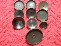
It is almost certainly "Design 13", used on all target sighted S&W hand ejectors from 1913 to 1932 (and on .32 frame hand ejectors from 1932 to 1942)---obviously in different sizes for the different frames.
The "Design 13" lingo is from Bob Neal's article The Evolution of Smith & Wesson Target Sights (a copy of which is available on this forum (somewhere)----and is the ONLY comprehensive work on the topic ever done.)
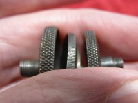
As an aside, it precedes #14, the so called "two screw sight"-------the very best sight S&W ever made in my opinion (in that it's infinitely adjustable and absolutely won't shoot loose when properly adjusted and locked---as opposed to the succeeding Micrometer click sight (which is not infinitely adjustable)---moving the point of impact yea far with each "click" (1/2" at 25 yards as I recall). The "two screw" is also the very first sight from S&W that won't shoot loose---after a mere 50 years of trying. (I suspect the "two screw" sight came into being following a brief meeting with the design folks during which Doug Wesson first announced the coming of the 357 Magnum (very much in need of a sight that won't shoot loose), and ending with the announcement that whoever comes up with the required design gets to keep their job.)
Ralph Tremaine
As another aside, the "two screw" sight moves the point of impact 1" with one full turn of an adjusting screw for each 10 yards of range. I suspect it's the same with preceding sights---only because I can't think of a reason why it would have been changed.
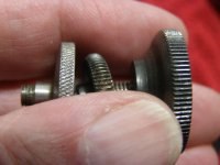
As yet another aside, the serial number on the bottom of this sight says it's for a K frame.
And now, sad to say, having gone back to Neal's article, his description of "Design 14" is incorrect---incomplete at best---never noticed it before---I knew what it was supposed to say, and didn't pay attention to what it does say-----familiarity breeds contempt for sure, I reckon.
BOTH aft screws on the "two screw" sight are used to adjust elevation AND to lock the sight. Works like so: Use the aft screw for the initial elevation adjustment (Get close!). Make the final elevation adjustment with the screw immediately in front of the aft screw. Now turn the aft screw counterclockwise as far as it will go. You're done. The screw just in front of the aft screw is pressing against the frame. The aft screw is pulling against the frame by way of its flange nut riding in a slot milled in the frame. This push/pull arrangement locks the adjustment in place---ABSOLUTELY!!