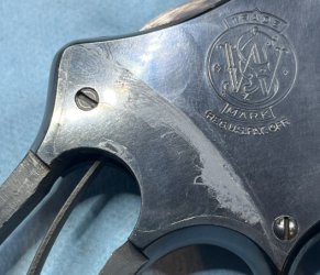
HomeSmith Tuneup: The Great .44 Extravaganza

Joined
Jul 25, 2017
Messages
1,101
Reaction score
6,517
Location
Arizona
How does HomeSmith spend his holidays? Working on guns, of course. Duh. :sneaky:

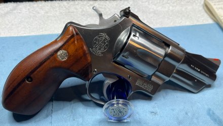
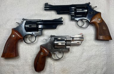
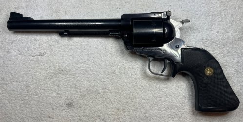
I've been spending so much time on TrainWrecks lately that I've built up a backlog of nice guns that needed attention. Ok - maybe not just "lately". One of the guns that needed help has been in the safe since last year and I'm just now getting around to it. My goal was to work on four .44's in one afternoon: a 624, a 24-3, a 1950 Target, and a Super Blackhawk.
IMG_6737a.jpg
IMG_6803a.jpg


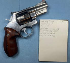
The 624 (code name: Thumper) was up first. As always, we started out with an inspection. The sing in various positions, the rear gauge, and the timing were all good. The cylinder gap was a tight .008" without the wedge and a loose .003" (but not .004") with the wedge, giving us .005" of endshake. The double action pull was 10 1/4 lbs, and the single action pull was 3 1/2 lbs. Nothing scary so far. Other than the sanded-down combat stocks, Thumper seems to be pretty much all original.
IMG_6741a.jpg

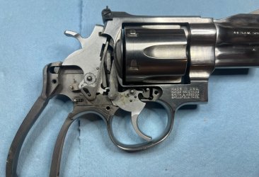
Inside, Thumper was very clean and very very dry. Usually when I open up a new gun it's full of goopy stuff that used to be oil. Not this one.
IMG_6742a.jpg

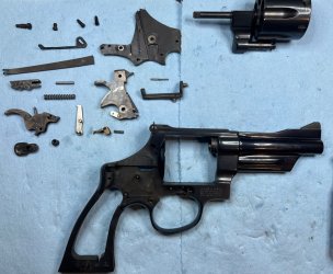
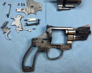
It only took a few minutes to move the insides to the outside and we were ready to begin the fluff and buff.
IMG_6743a.jpg

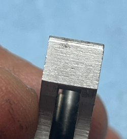
Judging by the lack of wear marks on the trigger bevel and the general cleanliness of the gun, I'd say that Thumper probably had only a box or two of ammo run through it before arriving at the Shotguncoach Home for Wayward Smiths.
IMG_6744a.jpg


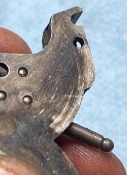
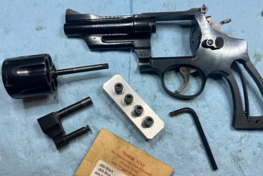
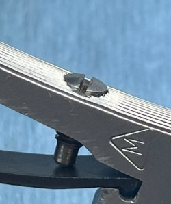
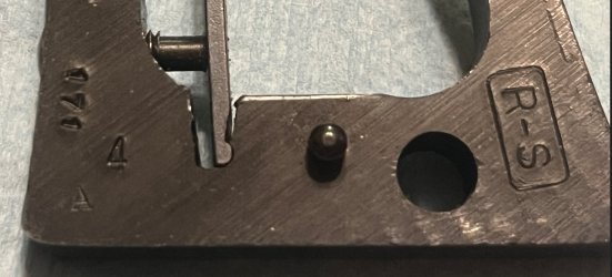
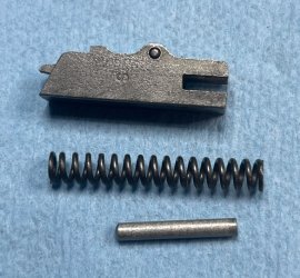
Everything was normal until I picked up the rebound slide unit, removed the spring, and something else fell out. Thumper had an internal trigger stop. I knew that Smith used them but I haven't run into one before. That's pretty spiffy.
IMG_6745a.jpg


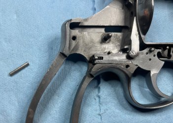
The cylinder stop, trigger, and rebound slide were all polished up and reinstalled......and of course I forgot the trigger stop.
IMG_6746a.jpg

I'm very interested in shooting Thumper with the trigger stop side-by-side with a gun that doesn't have the trigger stop so that I can learn just exactly what it does for the shooting experience. I can tell you that the reassembly experience is a PITA because the internal stop prevented me from using the ground-down-screwdriver-inside-the-spring trick to install the rebound slide and I ended up playing possum-up-the-gum-tree with the split end removal tool trying to keep the tool aligned with the spring coils. Several pinched fingers and one launched spring later, it was back together.

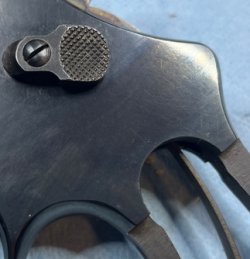
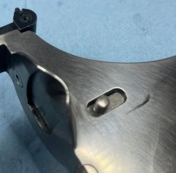
The yoke alignment was spot on, the ejector rod was straight (another clue that Thumper hasn't been shot much), and my good buddy Lance at Triggershims.com supplied a .003" cylinder shim that brought our endshake down to .002". The only other thing that needed to be fixed was to remove a bit of flash from the underside of the thumbpiece that had been rubbing on the frame.
IMG_6747a.jpg

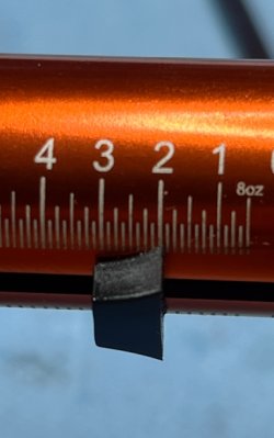
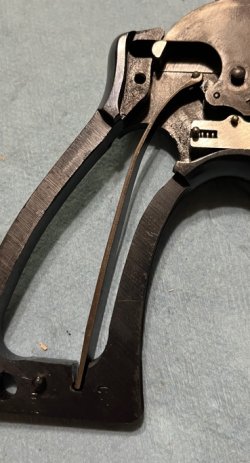
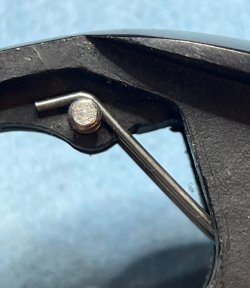
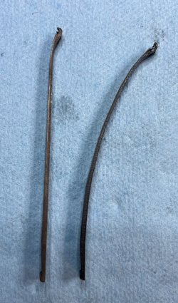
I wanted to try something a little different for the hammer spring. I've been reading about reshaping the spring to affect the hammer tension and trigger pull and this seemed like a good time to learn about that technique. I locked the spring into the big Wilton vise in the garage with only about an inch of spring sticking up and went after it with a 1 lb ball peen hammer. When I had a nice curve in the spring, I did a test fit in the gun, measured the hammer tension, and then went back to the vise, this time positioning the spring in the vise so that an additional inch stuck out. After 4 cycles of this, I ended up with a very curved spring that barely cleared the stock screw. This reshaped spring gave me 56 oz of spring tension (still a bit high) and a double action pull of just barely under 8 pounds. I'm going to try it this way and see how it works, then do some additional experimentation with reducing the radius of the curve near the hooks and increasing the bend to put the spring on the other side of the stock screw. (Thank you to Mr. Protocal_Design for the post about reshaping springs)

Original spring on the left, reshaped spring for Thumper on the right:
IMG_6755a.jpg

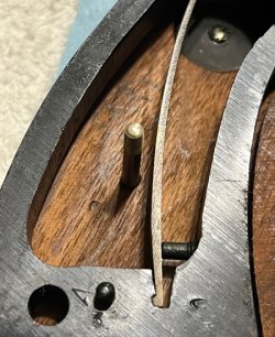
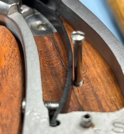
There's room here, but not much, and yes that strain screw is bottomed out - it sticks out of the frame just a bit.
IMG_6757a.jpg

IMG_6751a.jpg IMG_6752a.jpg

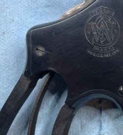
....and we were done with #1:
IMG_6760a.jpg
 
Register to hide this ad
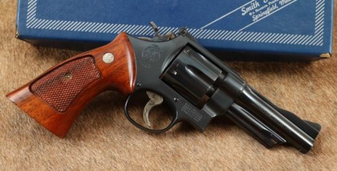
The 24-3 was purchased in March to make a pair with the 6" 24-3 that I bought myself for my birthday last year.

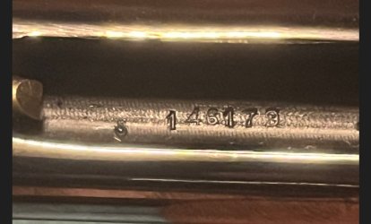
24-3 box.jpg

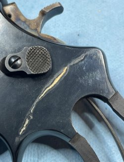
Removing the stocks to begin the inspection revealed what could have been a very unpleasant surprise on both sides of the frame, but happily a bit of oil on a rag wiped it right off.

IMG_6762a.jpg IMG_6763a.jpg

IMG_6765a.jpg IMG_6766a.jpg

Carrying on with the inspection, the yoke alignment was good, the ejector rod was straight, the rear gauge/headspace was in spec, the cylinder gap was exactly the same as it was with Thumper (.008" without the wedge, .003" with the wedge, endshake of .005" - and yes, I checked it twice because it was weird to have two exactly the same) and the timing........

Insert record scratch sound effect here.

The timing was at the very end of the hammer stroke on 4 chambers, and there was carry-up was late on the other 2 with both requiring just a touch more rotation for the cylinder stop to lock in when the hammer was at full cock.

So much for our "4 in one day" plan. At least now I know why I got it cheap. Let's move the insides to the outside and see what else we can learn.

IMG_6772a.jpg

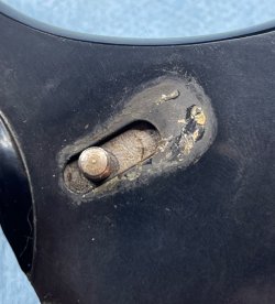
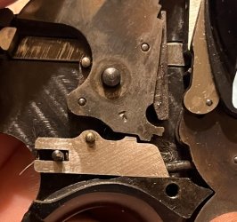
In addition to the late carry-up, the hammer, trigger, and sideplate all had stories to tell. The trigger was dragging on the frame, the hammer was dragging on the sideplate, and the rear leg of the bolt was making contact with the sideplate, and there was more of the mystery mung under the thumbpiece.

IMG_6776a.jpg IMG_6784a.jpg IMG_6785a.jpg IMG_6770a.jpg

At least the barrel appeared to be on straight.

One thing at a time......

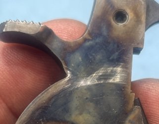
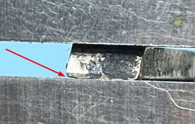
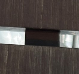
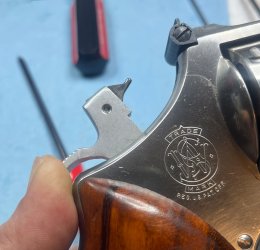
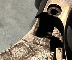
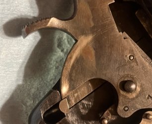
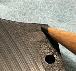
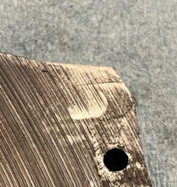
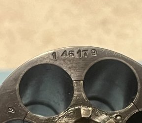
The cylinder stop was polished and installed, the trigger hook and bevel were polished, and it was time to look at the hand. I could tell that something wasn't quite right about it, but it wasn't really obvious until I put the hand into my calipers for a straight edge reference and viewed it under magnification. The contact portion of the hand was either damaged or had been "adjusted" by a monkey wearing boxing gloves.

IMG_6768a.jpgIMG_6769a.jpg

IMG_6767a.jpg

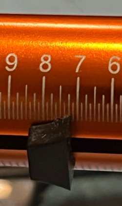
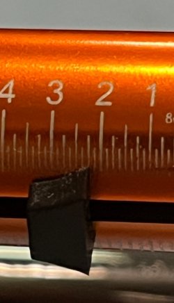
It was time to start looking for a replacement hand. The part of the original hand that was still square measured .093". Digging through the replacement hands gave me a couple of .095's, a .097, a handful of .098's, some big momma's that were over .100, and finally there was one lonely little white bag with a standard size hand in it. We were in business....

Here's the same view of the replacement hand in the calipers for comparison:
IMG_6773a.jpg
 
The new hand got a quick polish on the front surface that rides against the frame and was installed on the trigger using the patent-pending Fat Boy method. (If you don't know, you'll just have to read my other posts to find out what that is)

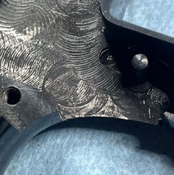
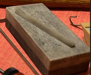
There was a burr on the inside of the frame that was causing the trigger drag, so that was removed with the end of a ceramic stone. The same stone was used to de-burr the frame around the hammer opening and the interior edges of the sideplate.

IMG_6779a.jpg

The rebound slide was polished up inside and out, an 11 lb Wolff rebound spring and the trigger stop this time were put inside, and the whole shebang was installed with only pinched fingers....no spring launches.

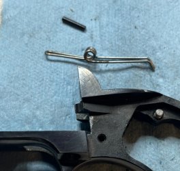
The cylinder was reinstalled and I did a quick timing check before putting in the rest of the pieces. I could feel just a slight bit of ratchet cutting happening, but the good news was that the cylinder stop popped into place well before the end of the trigger stroke. I have 5 more pictures that look exactly like this one, but you'll get the idea:
IMG_6780a.jpg


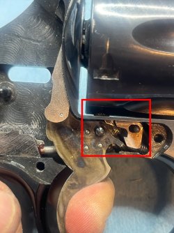
The bolt was installed after shortening and deburring the rear leg, the double action sear was polished and the hammer was installed, the mystery mung was cleaned off the frame under the thumbpiece, the thumbpiece was installed, and it was time to install the hammer spring and sideplate so that we could check the timing with everything in place. After the quick timing check, the cylinder was removed again and Lance from Triggershim.com provided yet another shim to correct the excess endshake.

IMG_6791a.jpg

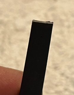
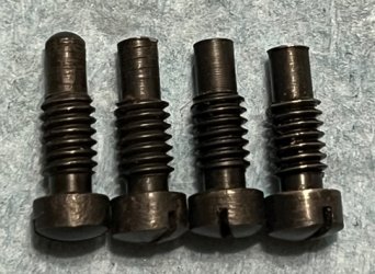
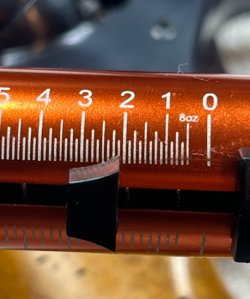
I wasn't able to measure the hammer tension during the inspection because it maxed out my 72 oz scale. Changing to a Wolff hammer spring with the original strain screw brought it down to "only" 68 ounces. Digging through the spare parts box turned up a replacement strain screw that was .005" shorter than the original, but that really didn't change the hammer tension at all. The original strain screw was placed in an envelope labeled with the serial number, and the replacement was chucked into a hand drill. The replacement was spun against a #2 file until it was .025" shorter than the original, which gave us 48 ounces of hammer tension with the Wolff spring.

IMG_6790a.jpg

A short happy dance was performed after checking the timing with all the pieces installed. Replacing the hand and correcting the endshake brought got rid of the late carry-up and the cylinder stop popped into place on all 6 chambers well before the end of the double action trigger stroke. A few dozen dry fires with snap caps in place finished the ratchet-to-hand fitting.

The replacement hammer spring and modified strain screw produced a double action pull of 7 lbs and a single action pull of 2 lbs.

IMG_6794a.jpg IMG_6795a.jpg

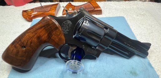
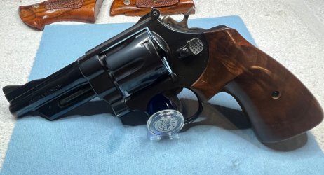
The N-frame diamond target stocks from the 50's and 60's fit my hands very well, but the oversize target stocks that Smith used in the 80's and 90's are simply too big for me. Rooting around in the pile produced an assortment of potential candidates, with the one that fit the best making the final cut.

IMG_6792a.jpg

IMG_6796a.jpg
IMG_6797a.jpg
The 624 was finished in an hour and 15 minutes....this one took almost 3 hours. So much for getting 4 done in a day.

Maybe I should start earlier than 3:30 in the afternoon next time. :unsure:

The 1950 Target is up next and will be an evening project for after work this week. Stay tuned......
 
The internal trigger stop is useless for the intended purpose because they are always too short to actually do that job. They are too short because each one would have to be hand fitted to each gun to actually work well. That is a finicky process, requiring very close fitment, something that is not going to happen on a production line. Also, over time, they can sometimes put a kink in the rebound spring retainer pin, depending on how hard the trigger is pulled during normal use.

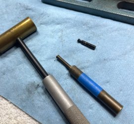
You will want to save these pins anyway, as they are the perfect diameter for replacement trigger pivot pins, which are an oddball, hard to find size. You only have to cut them to length for that use.
 
I didn't really have time tonight to start a new gun, so instead I fixed something that had been bothering me: I didn't like the way the strain screw stood proud of the grip frame on the 624. The stocks enclosed the front of the frame so it wasn't visible, but I knew it was there and it needed fixin. Working on this one again also gave me an excuse to make you guys wait a little longer to get a look at that sweet 1950 Target. :devilish:

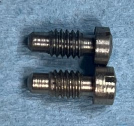
Anyway....I started by getting a spare screw out of the spare screw box so that I wasn't mucking about with the original. (Working on a spare also gave me the possibility of recovery if I royally screwed up the screw) This is when I learned that there are more than one head thicknesses on strain screws, and that the 624 already had the thin one.

IMG_6810a.jpg

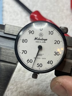
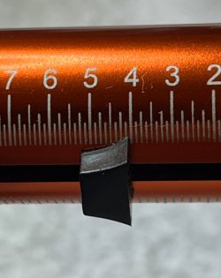
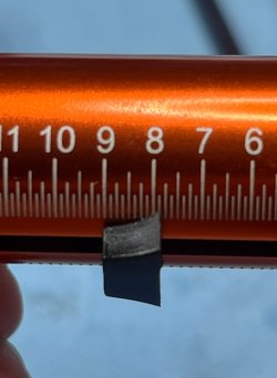
I did successfully locate a matching shallow head stainless screw that was a good candidate for the job. To measure the thickness of the convex screw heads I laid the screws flat long the edge of my calipers so that the screw itself became a "depth stop" to get as close as possible to measuring at the same point on the curve. The original screw head was .090" thick, the replacement was .089" thick. I was already ahead. ;)

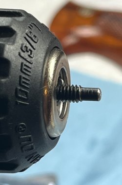
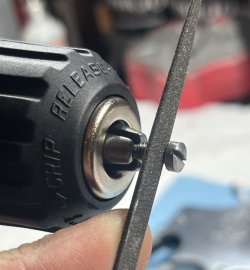
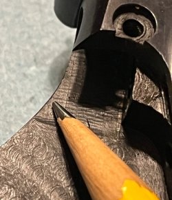
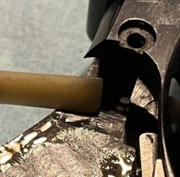
To cut the underside of the screw head, I chucked the unthreaded portion of the screw into a cordless drill motor and spun the screw against a file held against the bottom of the screw head. (It's a posed picture - I know the file isn't flat against the screw head. I didn't have enough hands to take a picture while I was doing the work)

IMG_6813a.jpg

By the third time I stopped to measure, the thickness of the screw head had been reduced by .011". A quick test fit on the frame showed a great improvement so it was time to move on to the problem I had just created.

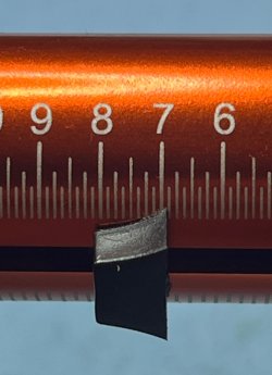
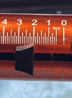
The original screw had a reach of .365". After cutting the head of the replacement screw, the reach was now .377". The longer reach would increase the hammer tension which would in turn increase the trigger pull. I needed to shorten the reach to maintain the trigger pull that I had, but with 56 ounces of hammer tension I had room to make it better. The screw was reversed in the drill motor and the tip of the screw was spun against a file until the reach was just a red one over .355".

IMG_6817.JPG

All this finagling with screw lengths resulted in changing the hammer tension from 56 ounces to 47 ounces. Coupled with the mass of that big N-frame hammer that should be plenty to set off non-magnum primers. If it turns out to be too light, I'll shave a bit more off the bottom of the screw head and extend the reach a bit.

Everything that is changed also changes something else, and the reduced hammer tension dropped the trigger pulls down to a level that I didn't like. The 11 pound rebound spring was replaced with a 13 pound spring to increase the pull weights to 7 lbs double action and 2 lbs 2 oz in single action with no push off. Now we had something nice.

IMG_6821a.jpg IMG_6822a.jpg

IMG_6819a.jpg

And....the screw that nobody will ever see fits better against the frame. ;)

IMG_6814a.jpg
 
This is one I never see on the Forums. If you need a longer strain screw, you can file the bottom of the head, as shown above, rather than putting a spent primer cup on the end. This would be a good way to deal with the Wolff Power Rib mainsprings.
 
Ok....so the whole rest and recovery thing after getting home from the hospital lasted for about 4 hours. After that I was done sitting on the couch and needed to do something other than watch TV and read.

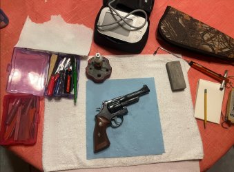
The directions from the Doc were to stay off my feet as much as possible. That meant that if I could sit down, I could work on guns. :unsure: I made a deal with SWMBO and agreed to check my stats more often and then set up my stuff on the kitchen table.

IMG_6894a.jpg


Some of you will recognize the extra piece of equipment at the top. If you don't, just wait. (By the way, if you're old enough to remember the Cowboy's winning the Superbowl, it's time to schedule that colonoscopy)

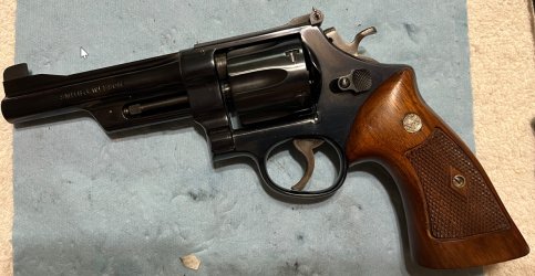
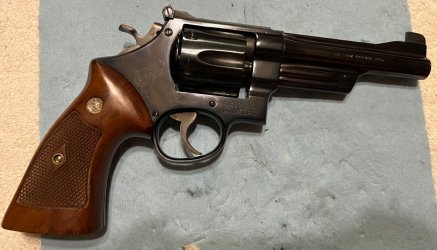
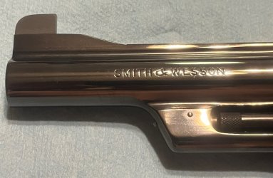
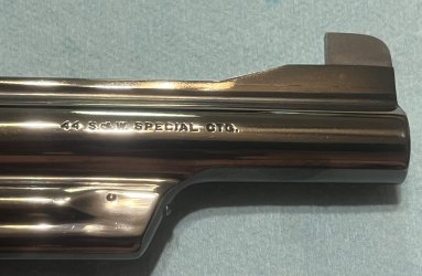
The next subject in The Great .44 Extravaganza is a 1950 Target in .44 special with a 5" barrel. No, it is not one of the 79 or so original 5" guns. This one came with a letter from Mr. Jinks plainly stating that the 5" barrel was aftermarket. If it had been original I would have needed to add a zero to the end of the price I paid.

IMG_6987a.jpg

IMG_6988a.jpg

IMG_6897a.jpg

IMG_6899a.jpg

IMG_6898a.jpg

IMG_6900a.jpg

IMG_6902a.jpg

IMG_6914a.jpg

I'm wondering if perhaps I should re-letter this one now that records have been digitized. The letter that came with it is from 2008 and I'm not sure if this little tidbit was recognized and included in that request:

IMG_6915a.jpg
 
The initial checks of timing, endshake, rear gauge, and cylinder gap all came out fine. The gap was a little large at .012" but I'm not going to try to hot rod this one and it should be fine. The double action pull was 9 1/4 lbs and the single action pull was just under 3 1/2 lbs. Not great, not terrible.

IMG_6917a.jpg IMG_6919a.jpg

The strain screw and sideplate were removed and the inspection continued. The first thing that jumped out was that the hammer spring was so long in relation to the hammer stirrup and frame that it was jammed in place and would not come out even with the strain screw all the way out. It had to be driven out with a punch.

IMG_6922a.jpg IMG_6923a.jpg

Listening to the rest of what the gun had to say, there was contact happening between the hammer and the sideplate, between the hammer and the bolt, between the hammer and the frame, between the rear leg of the bolt and the sideplate, and between the rebound slide and the sideplate. Whew. That's a lot of rubbing going on.

IMG_6924a.jpg

IMG_6956a.jpg

IMG_6925a.jpg

IMG_6926a.jpg
 
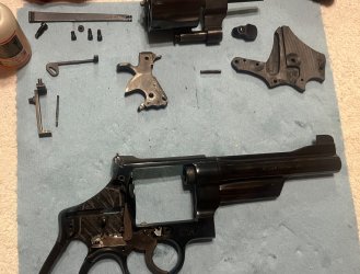
With all the pieces moved from the inside to the outside, it was time to start the rejuvenation process.

IMG_6933a.jpg


The end of a ceramic stone was used to clean up the area of the frame where the rebound slide would move, the sides and bevel of the cylinder stop were stoned smooth, the trigger hook and bevel were stoned (not the sear!!), and the leading edge of the hand was stoned smooth also. A few drops of oil in the right places and the first set of components were ready to go back in. There was a time that I was worried about what would happen if I took out that screw in front of the trigger guard, but now I sooooo much prefer to work on 4 and 5 screw guns. I know it was a lot of extra machining and labor costs, but the external screw cylinder stops are so much easier to work on.

IMG_6944a.jpg

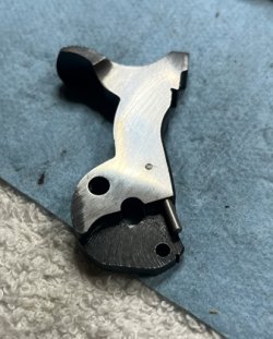
The rebound slide had the hammer seat polished, the 3 other sides polished, the sharp edges very slightly broken on the stone, and the inside edges deburred with a round file.

IMG_6945a.jpg IMG_6948a.jpg

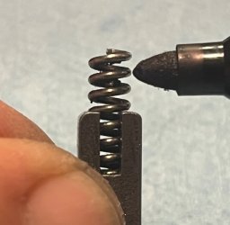
The rebound spring that was in the gun only had 16 coils, so somewhere along the way someone lightened the pull slightly. I've been replacing the rebound springs with Wolff reduced rate springs, but I wanted to try using Nelson Ford's method of "2 1/2 coils outside the box." Quite a few people say to just cut 2 coils off of the factory spring, but Nelson's method uses the rebound slide as the base of the measurement and however many coils go beyond the 2 1/2 coil count are clipped off. I marked the spring with a sharpie so I would know where to cut.

IMG_6949a.jpg

The cut spring was lubricated and installed in the rebound slide, then the two pieces were installed in the frame without the original trigger stop (thank you Mr. Protocall_Design!)

IMG_6954a.jpg

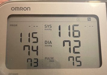
This was the halfway point, so it was time to check and make sure that the old ticker was still doing what it was supposed to do. It was, and I was cleared to continue.

IMG_6955a.jpg
 
Last edited:
The way I explained the last few days to my Grandkids was this: the top half and the bottom half of your heart are supposed to dance the Tango with each other, and it's the rhythm of that dance that makes the 'bump-bump' of your heartbeat. Well, on Wednesday night the top half of Grandpa's heart decided to do the Cotton Eyed Joe instead, and that's why Grandpa's chest hair looks like a checkerboard now.

Anyway, back to the 5" 1950....

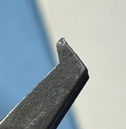
All sides of the bolt were smoothed with a safe edge #2 file, and the same file was used to remove a small amount of material from the rear leg of the bolt where it had been rubbing on the sideplate.

Several burrs were found inside the frame that had to be dealt with. There was a burr inside the bolt channel that was cleaned up with the edge of a thin wedge stone.....

IMG_6961a.jpg

IMG_6963a.jpg

IMG_6964a.jpg

and a burr along the top edge of the frame below the rear sight that was dragging on the hammer. That one was worked on with a small triangular stone.

IMG_6957a.jpg IMG_6966a.jpg
IMG_6968a.jpg

The double action sear on the hammer got a quick stoning, and then it was time to install the hammer and check the wink and verify that the required amount of dog hair had been trapped inside the rebound slide.

IMG_6969a.jpg

Side note: if you're working with stones and files around a gun with a finish that you care about, always keep your abrasive tools far away from the work area so you don't accidently rub up against one as you move the gun around.

IMG_6970a.jpg
 
The hammer spring was the next part of the project that needed work. Like the rebound spring, I've been using Wolff mainsprings in my square butt K-frames because they drop in and produce 48 ounces of hammer tension with the original strain screw. This time I wanted to try reshaping the hammer spring like I did earlier in the week on the 624. The too-long spring that came out was locked into a vise and the tapping began........and on the 4th tap, the whole damn thing broke in half.

IMG_6971a.jpg

A different original hammer spring was scrounged out of the pile, and the tap-reposition-tap-reposition-tap game was played using a large ball peen hammer and the big vise in the garage. The spring looked like this when I was done....note that there is no strain screw installed yet.

IMG_6972a.jpg

The original strain screw had been shortened to a reach of only .428" (probably to work with that mongo spring) and only produced 28 ounces of hammer tension with the reshaped replacement spring. Three other strain screws of various lengths were pulled from the pile for testing....

IMG_6980a.jpg

The screw with the .442" reach produced 36 ounces of hammer tension, the .454" screw produced 40 ounces of hammer tension, and the unmodified screw with a reach of .481 produced 52 ounces of tension. I used a file to shorten the reach on the long screw to .472" and bada-bing, we had 48 ounces of hammer tension and plenty of room around our stock screw.

IMG_6978a.jpg

We were getting close now.....

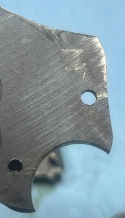
There was a good sized burr on the top rear of the sideplate just above where the rear leg of the bolt had been rubbing that was leaving marks on the hammer, so that was cleaned up using the triangle stone.

IMG_6924a.jpg

IMG_6959a.jpg

IMG_6981a.jpg

The hammer block was dropped in place, the sideplate was sideplated, the cylinder/yoke assembly was lubricated and installed, the screws were screwed, and the stocks were stocked. It was time to find out what we had done.

Double action:

IMG_6984a.jpg

Single action:

IMG_6985a.jpg

That worked for me. It was time to put away the tools and take a nap. Tomorrow we'll begin our first adventure inside a Ruger single action........
 
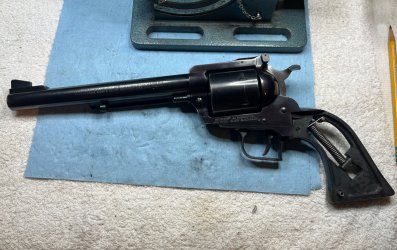
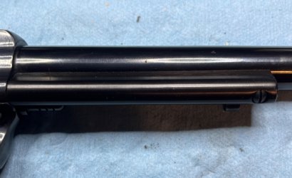
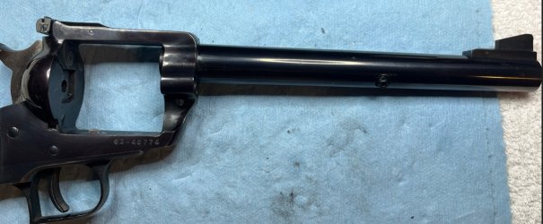
Our morning rest and recovery project was a new one for me: a Ruger single action, specifically this big boy:

IMG_7003a.jpg

Why did I feel the need to get inside this Super Blackhawk? Because I'm a snob and a 4 pound single action trigger pull offends me. ;)

IMG_7002a.jpg

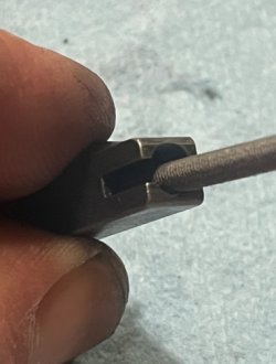
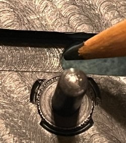
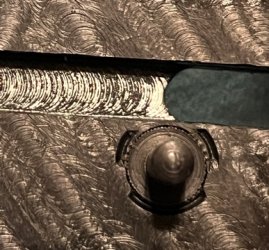
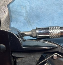
Before we get into this project, I want to take a moment and talk about screwdrivers. Interchangeable tip screwdrivers are popular for many reasons and I do have them, but it's important to look at more than just how the tip of the driver fits into the screw. Can you see the scratch happening in this picture?

IMG_7009a.jpg

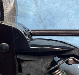
A set of properly sized hollow ground screwdrivers costs a bit of money, but they're worth it for the damage they don't cause:

IMG_7010a.jpg

Ok - soapbox put away now.

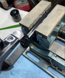
I knew from my recently acquired YouTube certification in Ruger single actions that I was going to need to secure the gun in a vise so that I could use both hands during this operation, so after verifying that the gun was empty and removing the cylinder, the ejector rod housing was removed from the barrel.

IMG_7013a.jpg

IMG_7014a.jpg

This allowed the center pin to be removed and the barreled action to be secured in my benchtop vise.

IMG_7016a.jpg

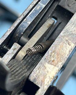
Ruger single actions use a coil spring and strut assembly to power the hammer which is very similar to the design of their double action revolvers. (There's one small exception that we'll get to later) After cocking the hammer, a paper clip is inserted into the takedown hole in the hammer strut to capture the coil spring and the hammer is allowed to return to the rest position.

IMG_7007a.jpg

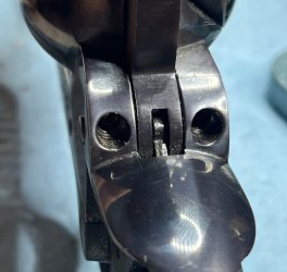
There are 5 screws that are used to attach the grip frame to the receiver. A pair on the sides of the hammer facing the shooter:

IMG_7011a.jpg

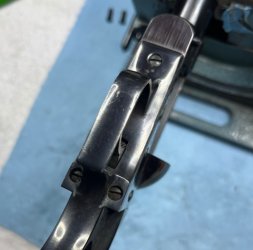
...and 3 on the bottom:

IMG_7017a.jpg

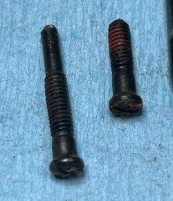
The pair that face the shooter match each other and are different from the other three. The one in front of the trigger guard is a little short guy that will only fit in that position. The two that come up from the bottom are different shapes. The one with the long snout goes on the side with the loading gate.

IMG_7019a.jpg

With a little wiggling and jiggling, the grip frame separates from the receiver.

IMG_7020a.jpg

There are two spring and detent assemblies that you'll need to keep track of as the grip frame comes off. The larger of the two is for the cylinder stop and will probably stay on the receiver:

IMG_7027a.jpg

The smaller one is to put tension on the hand (or pawl, as Ruger calls it) and sticks out of the back of the receiver next to the hammer. If you get everything put back together and the cylinder will only rotate if the muzzle is pointed down, this is the piece you forgot to put back in. I didn't do that, but I did have my own set of adventures during reassembly.

IMG_7032a.jpg
 
Last edited:
This is as far as you need to go if you're only installing a spring kit. I went all the way to the bare frame because I'm and idiot and a glutton for punishment.

The V-shaped spring on the loading gate side of the bottom of the receiver has a leg on it that fits into a slot in the trigger pin to retain it. The videos you'll watch just show the person pushing the spring down with their finger and sliding the pin out.


IMG_7034a.jpg

Yeah right. This gun hasn't been taken apart since it was made. My pins did not just slide out.

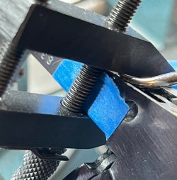
In order to have both hands available to use a hammer and punch, I used a small parallel clamp with a hook tool captured underneath it to compress the V spring and hold it there while I messed with the pin.

IMG_7039a.jpg

IMG_7040a.jpg

This arrangement allowed me to use both hands to gently drive out the trigger pin with a brass punch.

IMG_7041a.jpg

Once that pin was out, everything else really did just fall out on the bench...

IMG_7042a.jpg

I don't have a Ruger single action adapter for my Power Custom sear jig, so I didn't try to do anything with the sear. The work done to the insides consisted only of cleaning, lubrication, a light stoning of areas that were obviously rubbing (not many), and a cleanup of the normal Ruger oxidation on the hammer.

IMG_7043a.jpg

The tube videos show installing the hammer and pawl first, then installing the trigger and transfer bar. I was simply not able to snake the transfer bar around the hammer, so I assembled all 4 pieces outside of the gun and dropped them in as a unit. I apologize for not getting a picture of that operation - I needed all three hands and didn't have a spare for the camera.

The round knob on the side of the cylinder stop was inserted into the V of the V-spring and those two parts were placed into position. Reinstalling the now clean and lubricated pins was much easier than removal, and everything slid into place without needing to use the parallel clamp again.

IMG_7045a.jpg
 
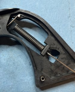
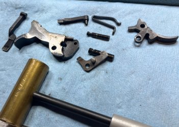
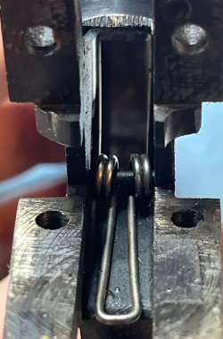
Going back to the grip frame, the trigger return spring is a coil spring with a tongue that sticks forward and sits under the trigger, two legs that hang on pegs in the frame, and a cross pin through the coil that holds it all in place.

IMG_7022a.jpg

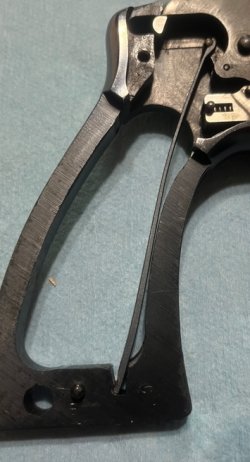
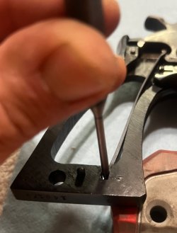
IMG_7023a.jpg

IMG_7025a.jpg

Popping the legs off the studs removes all tension on the spring, which allows the pin to move and everything falls out onto the bench.

IMG_7046a.jpg

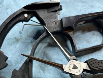
I replaced the original spring with a Wolff reduced power return spring. Orient your new spring with the coils facing UP and the feet at the end of the legs facing DOWN. An appropriately sized punch used as a slave pin/guide makes reassembly much easier.

IMG_7047a.jpg

And a small pair of needle nose pliers is handy for putting the legs back on the studs.

IMG_7048a.jpg

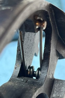
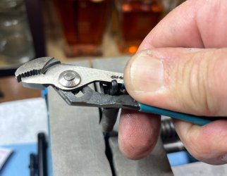
The hammer spring was replaced by holding the strut in the vise and compressing the spring retainer between the handles of a set of miniature channel locks.

IMG_7050a.jpg

Which allowed the spring to be unsprung without going sproing.

IMG_7049a.jpg

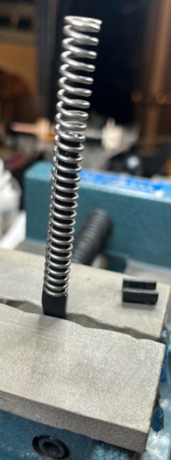
The Wolff reduced power hammer spring was much easier to compress....the same technique was used to reassemble the hammer strut assembly and reinsert the paper clip.

A small dab of grease was put into the hole in the grip frame where the cylinder stop spring sits so that it would stick in place when the grip frame was upside down.

IMG_7029a.jpg

....and the grip frame was just dropped into place on the receiver and we were done. :rolleyes:

No. We were not.

Capturing the pawl spring and the trigger return spring in the right places while keeping the cylinder stop plunger aligned takes a bit of practice. A small screwdriver is helpful to hold the trigger return spring down so that it will slip under the trigger.

The first time I had to take it all apart again was because I didn't get the cylinder stop plunger aligned correctly and the cylinder stop just sort of flopped around, not stopping anything.

The second time I had to take it apart again was because I forgot to put the hammer spring/strut assembly into the grip frame before installing it on the receiver. This is not a Security Six and the strut assembly will not come out (or be installed) unless the grip frame is completely removed.

The third time I had to take it all apart again was because I installed the hammer strut assembly upside down and the hammer would not move to the full cock position. Mark the orientation of the hammer strut before you take it out. The round part goes up. :cautious:

Finally everything was together correctly. The trigger triggered, the cylinder stop stopped, the loading gate gated, the pawl pawled, and the hammer hammered. The ejector rod housing was installed on the barrel and it was time to do the real function checks.

No it wasn't.

The fourth time got to take it apart again was because the center pin is captured by the ejector rod housing and can only be removed/installed if the housing is removed. Grrr.

IMG_7056a.jpg

IMG_7057a.jpg

Ok.....now it was actually all back together and could be function checked. The timing was spot on, everything moved as it should and the trigger felt much better. How much better? This much better:

IMG_7058a.jpg

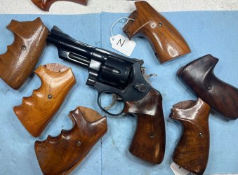
The pile was stirred, Bill Ruger's name was taken in vain, a set of Rossi stocks was ceremoniously burned, and a set of Herrett's stocks for a Super Blackhawk rose to the top.

IMG_7059a.jpg

IMG_7060a.jpg

Time for a nap....
 
Here's a little bonus .44 Special goodness for you...

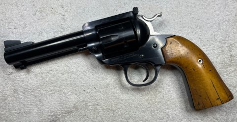
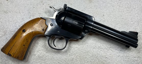
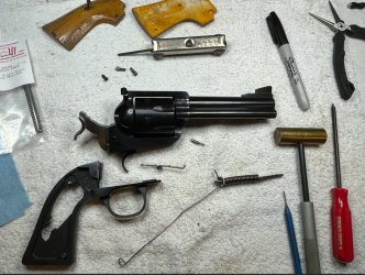
Now that I've been inside a Ruger single action and new what to expect, I decided to give my .44 Special Bisley Blackhawk a tuneup as well.

IMG_7068a.jpg

IMG_7069a.jpg

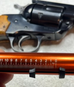
Bisley Bob also had the same atrocious 4+ pound trigger....

IMG_7070a.jpg

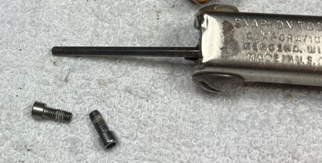
Once the grip panels were off I discovered a slight challenge: The Bisley grip frame is attached at the top rear with a pair of 7/64" allen head cap screws instead of the normal slotted screws used on the standard Blackhawk frame.

IMG_7076a.jpg

Guess what size allen wrench I did not have in my 'smithing tools.......I had to go all the way back to a previous life to find one.

IMG_7077a.jpg

IMG_7078a.jpg

With the allen screws out, the rest of the grip frame removal was the same as the Super Blackhawk.

IMG_7080a.jpg

With one exception: this time I remembered to mark the orientation of the hammer spring strut:

IMG_7079a.jpg

I didn't take this one as far apart as the Super because I didn't want to fight with that spring again. Thank you to Professor Cassidy for pointing me towards the RW Grips 'third hand'....I have one in my cart while I decide whether or not I want a brass Keith #5 grip frame to go with it. ;)

The spring swap provided a trigger pull of just over 2 lbs, but I will have to get into this one again eventually. The pull is light but it is definitely not 'crisp'. There is approximately 87 miles of creep before the sear lets go and that's going to bother me. I'm not ready to do that today - I need a few tools and I'd like to get a used hammer and trigger to practice on first. I have Smith & Wesson spares out the wazoo but not for Ruger single actions. You'll see this gun again eventually...

IMG_7081a.jpg

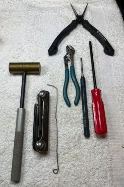
Working on these last 2 guns has been interesting. Not only are the pieces/parts different, the tools are different. This is very much not what I'm used to seeing on the bench:

IMG_7082a.jpg
 
Back
Top